Synth
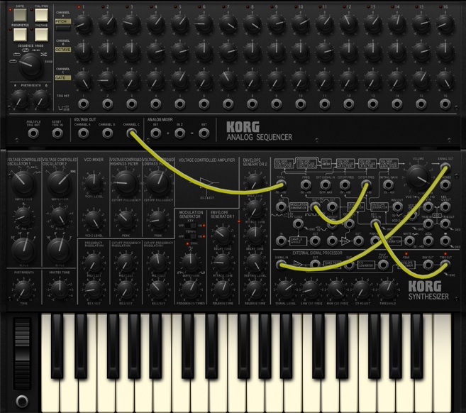
This screen shows the synthesizer and sequencer arranged vertically. To change the area that’s visible, slide up or down on any location other than a knob or switch. Using this screen alone, you can control all of the parameters for the synthesizer and sequencer. If you want to concentrate on editing the MS-20, zoom the display by turning on the “ZOOM MS-20” button located in the SYNTH EDIT section at the top of the screen. If you turn on “EFFECT” located below it, the synthesizer effect panel will be shown.

MS-20 CONTROL PANEL
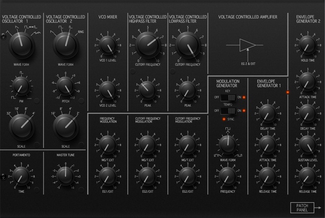
Use the knobs and switches to edit the MS-20’s sound.

VOLTAGE CONTROLLED OSCILATTOR 1 / 2
| WAVE FORM | Specifies the waveform for oscillators 1 and 2. |
| PW | Specifies the pulse width when a pulse waveform is selected for oscillator 1. |
| PITCH | Specifies the pitch of oscillator 2. |
| SCALE | Specifies the pitch of oscillators 1 and 2 in units of an octave. |
PORTAMENTO
| TIME | Specifies the portamento time (the time over which the pitch smoothly changes from one note to the next different note). Higher settings will produce slower pitch change. |
MASTER TUNE
| MASTER TUNE | Adjusts the pitch of the oscillators in units of one cent. The range is +/-100 cents. |
VCO MIXER
| VCO1 LEVEL | Adjusts the output level of oscillator 1. |
| VCO2 LEVEL | Adjusts the output level of oscillator 2. |
FREQUENCY MODULATION
| MG/T.EXT | Adjusts the depth of modulation that’s applied by the modulation generator to the pitch of oscillators 1 and 2. |
| EG1/EXT | Adjusts the depth of modulation applied by EG1 to the pitch of oscillators 1 and 2. |
VOLTAGE CONTROLLED HIGHPASS FILTER
| CUTOFF FREQUENCY | Adjusts the cutoff frequency of the high-pass filter. |
| PEAK | Boosts the region around the cutoff frequency where the low frequency region is being cut. Setting this knob near the maximum setting will cause the filter to self-oscillate. |
VOLTAGE CONTROLLED LOWPASS FILTER
| CUTOFF FREQUENCY | Adjusts the cutoff frequency of the low-pass filter. |
| PEAK | Boosts the region around the cutoff frequency where the high frequency region is being cut. Setting this knob near the maximum setting will cause the filter to self-oscillate. |
CUTOFF FREQUENCY MODULATION (HIGHPASS FILTER)
| MG/T.EXT | Adjusts the depth of modulation applied by the modulation generator to the cutoff frequency of the high-pass filter. |
| EG2/EXT | Adjusts the depth of modulation that’s applied by the EG2 or external input to the cutoff frequency of the high-pass filter. |
CUTOFF FREQUENCY MODULATION (LOWPASS FILTER)
| MG/T.EXT | Adjusts the depth of modulation that’s applied by the modulation generator to the cutoff frequency of the low-pass filter. |
| EG2/EXT | Adjusts the depth of modulation that’s applied by the EG2 or external input to the cutoff frequency of the low-pass filter. |
MODULATION GENERATOR
| KEY SYNC | If this is on, the phase of the modulation generator will be reset at each note-on. |
| TEMPO SYNC | If this is on, the modulation generator will synchronize to the tempo of the sequencer. |
| WAVE FORM | Specifies the waveform of the modulation generator. |
| FREQUENCY/TIMES | If “TEMPO SYNC” is on, this specifies the rate of the modulation generator. If “TEMPO SYNC” is off, this specifies the frequency of the modulation generator. |
ENVELOPE GENERATOR 1
| DELAY TIME | Specifies the time from triggering until the EG begins to operate. |
| ATTACK TIME | Specifies the time from triggering until the attack level is reached. |
| RELEASE TIME | Specifies the time of the release starting when triggering is removed. |
ENVELOPE GENERATOR 2
| HOLD TIME | Specifies the time where triggering will be held after the trigger signal has ended. |
| ATTACK TIME | Specifies the time from note-on until the attack level is reached. |
| DECAY TIME | Specifies the time from when the attack level is reached until the sustain level is reached. |
| SUSTAIN LEVEL | Specifies the sustain level. |
| RELEASE TIME | Specifies the time from note-off until the level decays to zero. |
PATCH PANEL
Shows the synth patch screen.
MS-20 PATCH PANEL
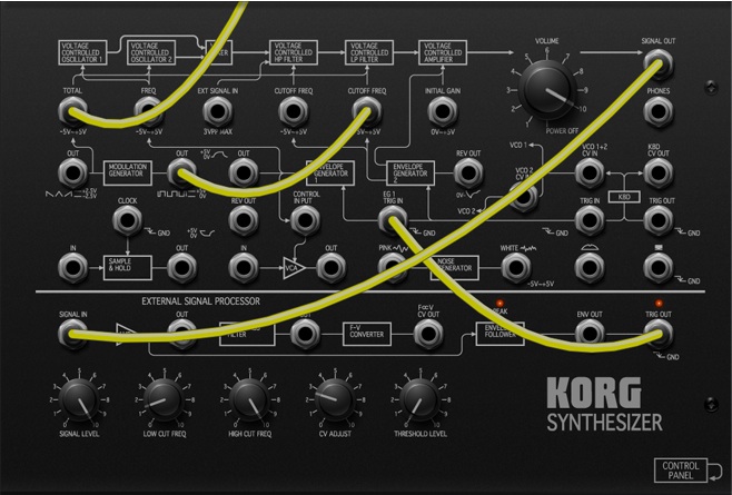
Patching allows you to edit synthesizer sounds in a more sophisticated way. If “ZOOM MS-20” is on, you can also view the sequencer’s patch panel by sliding up or down on any location other than a jack or knob.

Patch jacks
These are input and output jacks for each module. By connecting these jacks with patch cables you can modify the sound in a wide variety of ways.
You can also connect these with the sequencer’s jacks. You can’t connect outputs to outputs, or inputs to inputs.
VOLUME
Adjusts the output level.
EXTERNAL SIGNAL PROCESSOR
This converts the pitch of the external signal input to “SIGNAL IN” into a control signal, or extracts an envelope or trigger from the external signal.
| SIGNAL LEVEL | Adjusts the level of the signal from “SIGNAL IN.” Adjust this so that the peak indicator lights briefly when the input signal is at its loudest level. |
| LOW CUT FREQ | Adjusts the low cutoff frequency of the band-pass filter. |
| HIGH CUT FREQ | Adjusts the high cutoff frequency of the band-pass filter. |
| CV ADJUST | Adjust this so that the input signal is the same pitch as the synthesizer’s output signal. |
| THRESHOLD | Adjusts the threshold level where a trigger signal will be extracted. |
SEQUENCER
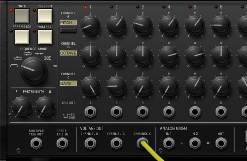
You can use the sequencer to control the MS-20, causing it to play sounds. You can also use it to vary parameter values at each step.

Channel set
NOTE
Assigns channels A/B/C to control the pitch etc.
| CH A: PITCH | Controls the pitch. |
| CH B: OCTAVE | Controls the pitch in one-octave units. |
| CH C: GATE | Controls the duration of notes. |
VOL/PAN
Assigns channels A/B to control the volume and pan.
| CH A : VOLUME | Controls the volume. |
| CH B : PAN | Controls the pan. |
PARAMETER
Assigns channels A/B/C to control the synth or effects.
| CH A: (PARAM1) | Controls a specified parameter of the synth or effect. |
| CH B: (PARAM2) | Controls a specified parameter of the synth or effect. |
| CH C: (PARAM3) | Controls a specified parameter of the synth or effect. |
VOLTAGE
Assigns channels A/B/C to control parameters via the VOLTAGE OUT jacks.
| CH A: (VOLT.A) | Controls the parameter you’ve patched from VOLTAGE OUT. |
| CH B: (VOLT.B) | Controls the parameter you’ve patched from VOLTAGE OUT. |
| CH C: (VOLT.C) | Controls the parameter you’ve patched from VOLTAGE OUT. |
SEQUENCE MODE
| FORWARD | Move from left to right. |
| BACKWARD | Move from right to left. |
| ROUND | Move from left to right, and then back. |
| TO CENTER | Play steps from both ends toward the center. |
| ODD/EVEN | Play odd-numbered steps, then play even-numbered steps. |
| RANDOM | Play steps randomly. |
PORTAMENTO A/B
Specify the portamento time applied to the values of each step for channels A/B. Higher settings make the value change more slowly.
Channel settings
CHANNEL A : PITCH
| Chromatic | The pitch will change in chromatic steps. |
| Smooth | The pitch will change smoothly. |
CHANNEL A/B/C : (PARAMETER)
Specify the desired synth or effect parameter.
CHANNEL A/B/C : (VOLTAGE)
Specify the range of values covered by each channel’s knobs.
| “-5..+5” | This allows the value to be varied more greatly. |
| “-1..+1” | This allows the value to be specified in finer detail. |
| “0..+5” | This allows change in only the positive direction. |
Step knobs
Specify the value of each step.
TRIG OUT
These jacks output an independent trigger for each step.
MULTIPLE TRIG OUT
This jack outputs a trigger signal each time the sequencer proceeds to the next step.
RESET TRIG IN
You can use this jack to change the number of steps. Connect a patch cable from the “TRIG OUT” of the last step to this jack.
VOLTAGE OUT
These jacks are the outputs of each channel.
ANALOG MIXER
This allows you to sum the output voltages of the channels. For example if you set channel A VOLTAGE to “-5…+5” and channel B VOLTAGE to “-1..+1,” you can sum the outputs of these channels to obtain more precise control of the values.
EFFECT
This area is shown on the upper right side of the screen; it lets you apply various effects to the sound. An explanation of the effect types and parameters is provided here.

KEYBOARD
This is a keyboard for performance. You can play notes by tapping or sliding on the keyboard. You can also change the keyboard’s width or the range that is shown.

REC
By performing while this is on, you can record phrases to the sequencer. The recorded pitches can later be edited in the sequencer.
The timing where the recorded notes will sound is automatically quantized according to the sequencer’s tempo and the step interval.
OCTAVE
Switches the range of the performance keyboard in one-octave steps.
| DOWN | Lowers the range one octave. |
| UP | Raises the range one octave. |
KEYBOARD POSITION
Use the slider or buttons to specify the keyboard note range that you want to use, in units of white keys.
KEYBOARD WIDTH
Specifies the width of the keys.
| THICK | Somewhat thicker than NORMAL. |
| NORMAL | The normal width. |
| THIN | Somewhat thinner than NORMAL. |
This setting will not affect the 37-note keyboard in the SYNTH screen.
Keyboard
You can perform by tapping or gliding over the keyboard.
Modulation wheel
You can use this to continuously control a parameter value while you perform. The parameter to be controlled can be specified individually for each patch.
Momentary switch
This switch lets you turn a value such as EG triggering on or off. The parameter to be controlled can be specified individually for each patch.
KAOSS PAD
By sliding over these pads, you can control the parameters that are assigned to the X (horizontal) and Y (vertical) axes of each pad. You can use this to play sounds or to modify parameter values. For example, sliding horizontally on the left Kaoss pad will change the pitch, while sliding vertically will change the duration of the notes while you perform.

REC
If you perform with this turned on, the phrases and tonal changes that you perform will be recorded on the sequencer. Afterward, you can use the sequencer to edit the recorded parameters.
KAOSS PAD L (left)
You are free to assign the X and Y axes to control the desired parameters. Use “SETTINGS” to assign parameters to X and Y.
KAOSS PAD R (right)
NOTE is assigned to the X-axis, and GATE is assigned to the Y-axis. Use “SCALE” to specify the key and scale.
X-axis parameter
Indicates the parameter that’s assigned to the X-axis.
Y-axis parameter
Indicates the parameter that’s assigned to the Y-axis.
SCALE
Specifies the key and scale for the pitch that’s controlled by KAOSS PAD R.
Scale list
| No. | Display | Scale name | Scale:Key C |
|---|---|---|---|
| 1 | Chromatic | Chromatic | C Db D Eb E F Gb G Ab A Bb B C |
| 2 | Ionian | Ionian | C D E F G A B C |
| 3 | Dorian | Dorian | C D Eb F G A Bb C |
| 4 | Phrygian | Phrygian | C Db Eb F G Ab Bb C |
| 5 | Lydian | Lydian | C D E F# G A B C |
| 6 | Mixolydian | Mixolydian | C D E F G A Bb C |
| 7 | Aeolian | Aeolian | C D Eb F G Ab Bb C |
| 8 | Locrian | Locrian | C Db Eb F Gb Ab Bb C |
| 9 | Major Blues | Major Blues | C Eb E G A Bb C |
| 10 | Minor Blues | Minor Blues | C Eb F Gb G Bb C |
| 11 | Diminish | Diminish | C D Eb F F# G# A B C |
| 12 | Combi Diminish | Combination Diminish | C Db Eb E F# G A Bb C |
| 13 | Major Penta | Major Pentatonic | C D E G A C |
| 14 | Minor Penta | Minor Pentatonic | C Eb F G Bb C |
| 15 | Raga 1 | Raga Bhairav | C Db E F G Ab B C |
| 16 | Raga 2 | Raga Gamanasrama | C Db E F# G A B C |
| 17 | Raga 3 | Raga Todi | C Db Eb F# G Ab B C |
| 18 | Spanish | Spanish Scale | C Db Eb E F G Ab Bb C |
| 19 | Gypsy | Gypsy Scale | C D Eb F# G Ab B C |
| 20 | Arabian | Arabian Scale | C D E F Gb Ab Bb C |
| 21 | Egyptian | Egyptian Scale | C D F G Bb C |
| 22 | Hawaiian | Hawaiian Scale | C D Eb G A C |
| 23 | Bali Pelog | Bali Island Pelog | C Db Eb G Ab C |
| 24 | Japan | Japanese Miyakobushi | C Db F G Ab C |
| 25 | Ryukyu | Ryukyu Scale | C E F G B C |
| 26 | Wholetone | Wholetone | C D E Gb Ab Bb C |
| 27 | m3rd Interval | Minor 3rd Interval | C Eb Gb A C |
| 28 | M3rd Interval | 3rd Interval | C E Ab C |
| 29 | 4th Interval | 4th Interval | C F Bb C |
| 30 | 5th Interval | 5th Interval | C G C |
| 31 | Octave | Octave Interval | C C |
SETTINGS
This lets you assign the parameters that you want to control from the sequencer to the X and Y axes of KAOSS PAD L.